Overview
During this project, I collaborated with a team to develop assistive technology tailored to a particular user group. We focused on designing a tripod attachment for individuals with cerebral palsy or wrist tendonitis, enabling them to take photos with ease. Our objective was to manufacture a prototype of the product within a budget of $200, while also ensuring that our design could be mass-manufactured efficiently.
Design Process
We began our design process by crafting a user survey. Our interviews revealed that small components of the tripod, like wheels and levers, posed significant challenges for our target population. Consequently, we made it a priority to eliminate the need to screw a camera onto the tripod, as well as to adjust knobs for swivel and tilt. We brainstormed potential mechanisms for each function and utilized metrics to guide our final design selection.
Product Features
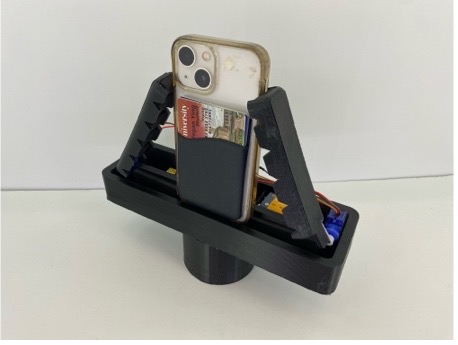
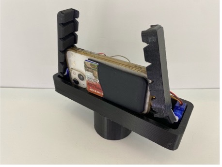
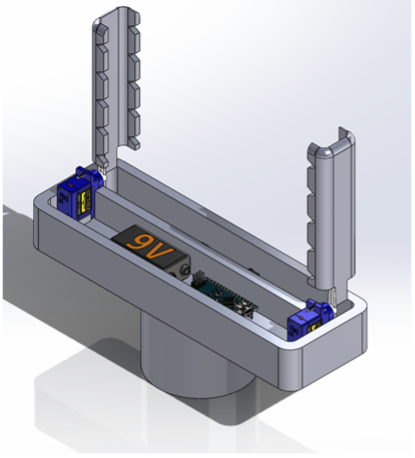
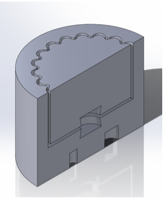
Our final product is an attachment designed to seamlessly integrate with any tripod. It automates the process of securing a phone within a tripod, preventing the user from needing to apply any additional force and reducing the need for steady hands. The base of our product is made from ABS, a rigid material, and houses an IR sensor. When the sensor detects the presense of phone, a pair of wings, which are powered by micro servos, a nano board, and a 9V battery, open and close to secure the phone within the slot. To remove the phone after use, users can simply pull it out of the subassembly. The base slot is lined with foam and the wings are made from a flexible material called TPU, allowing the attachment to accommodate phones of varying sizes.
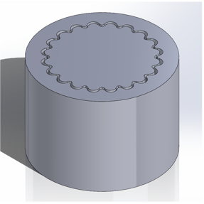
In addition, our design incorporates an interface piece attached beneath the base. The inner interface is made from TPU, while the outer portion is made from ABS. Both components feature rounded gear teeth for easier swiveling and locking. As a result, users can twist the subassembly without needing to loosen any knobs. Furthermore, we integrated magnet holes into our design. These magnets enable the inner and outer pieces to snap together securely, while also allowing the parts to be easily dismantled.
Analysis Process
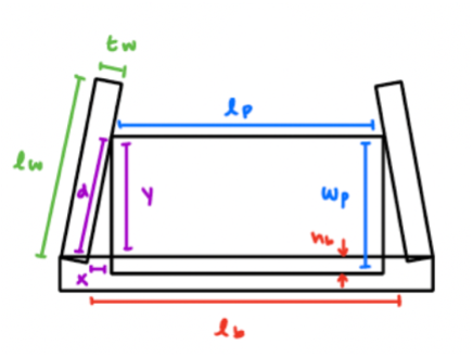
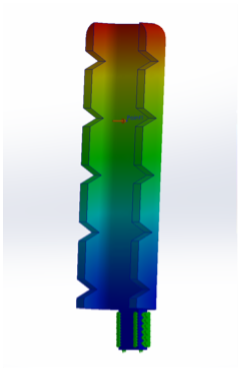
Our team conducted both hand calculations and a Finite Element Analysis (FEA) simulation on the wings of our product. We opted for a high factor of safety to ensure durability, allowing the product to undergo many opening and closing cycles before needed to be replaced. After finalizing our design, we estimated the cost of our product by obtaining a quote for components from Protolabs, based on a sample quantity of 50. Although our prototype was fabricated using 3D printing, we determined that injection molding would be the preferred manufacturing method due to its efficiency, enabling more parts to be produced at a lower cost pepr unit. According to our calculations, the total cost of manufacturing and assembling our product would be approximately $58. Thus, we set the price of our attachment at around $62, allowing for a 7% profit margin.
Results
My team successfully fabricated a fully functional model of our tripod attachment. Through this project, I developed a better understanding of the various aspects of mass manufacturing, such as material selection and manufacturing processes. Additionally, I gained hands-on experience with integrating electronics into mechanical systems, further enhancing my skill set.
