Overview
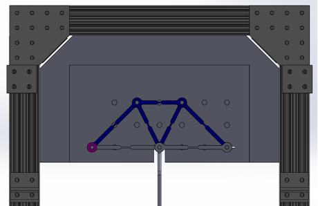
In this project, I worked with a team to design a truss structure. Our objective was to apply structural analysis techniques to engineer a truss capable of withstanding a 40-pound load, while also minimizing its weight. We generated our parts and assemblies using SolidWorks, and used a laser cutting machine to fabricate our truss members.
Design Process
My team began the design phase by sketching nine potential structures that satisfied the truss design requirements. We then calculated the force exerted on each member within these configurations when subjected to a 40-pound load at the center. This allowed us to evaluate the strength-to-weight ratio of each truss design. We then selected the configuration with the highest strength-to-weight ratio as our final design. Following this decision, we conducted stress analysis and failure safety assessments to determine the required width of the members to withstand a 40-pound load. Subsequently, we used SolidWorks to create a Computer-Assisted Design (CAD) model of our final design.


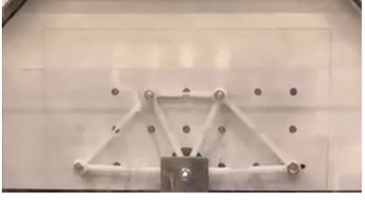
After finalizing the dimensions of our truss members, we proceeded to generate DXF files for each required compoenent. We imported these files into CorelDRAW software, adjusted settings to facilitate cutting through acrylic material, and executed the laser cutting process. After the truss members were successfully fabricated, we assembled our truss structure using screws and bolts.

Results
On testing day, our truss failed at approximately 38 pounds. Through this project, I was able to apply fundamental mechanical engineering principles, such as 2D equilibrium, stress analysis, and failure theory, to a real-world application. Additionally, I gained valuable insights into the use of CAD software and laser cutting machines for prototyping.
